Making access control installation mistakes is easier than most people think — and the consequences range from annoying to genuinely dangerous. A misaligned maglock, an overloaded power supply, or a missing wire label can leave a door unsecured, damage your equipment, or cost you hours of troubleshooting on a job site.
This guide covers the 7 most common access control installation mistakes made by technicians and DIY installers across the United States and Canada — along with practical, step-by-step advice to prevent each one.
Whether you're installing your first electromagnetic lock or managing a multi-door commercial system, these principles will help you get the job done right the first time.
Table of Contents
- Not Properly Aligning the Armature Plate
- Installing Products Without Testing Them First
- Not Checking Wires for Continuity
- Using an Inadequate Type of Wire
- Not Labeling the Wires
- Overloading the Power Supply
- Ignoring Wiring Instructions and Diagrams Final Thoughts
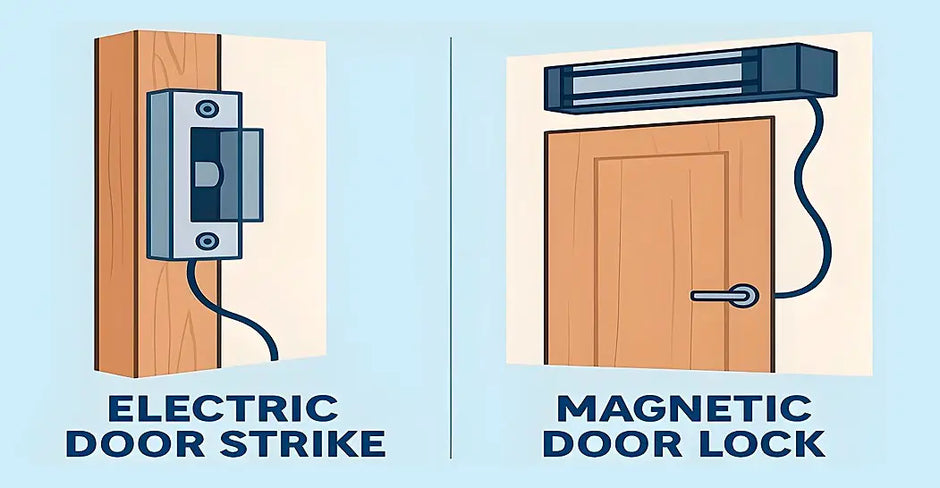
Mistake #1: Not Properly Aligning the Armature Plate with the Magnet

Why It Happens
Maglock installation looks simple on the surface — bolt the magnet to the frame, attach the armature plate to the door, run the wires. Many installers rush through the mechanical mounting without realizing that even a 1–2 mm misalignment can slash the lock's holding force dramatically.
A common error involves the rigid mounting of the armature plate.
Installers often tighten the mounting bolt to the point of immobility, assuming a firmer mount is superior. In reality, standard practice requires the armature plate to "float" or pivot slightly.
This pivot action is facilitated by the inclusion of specialized rubber washers behind the plate, allowing it to self-align and sit perfectly flat against the magnet face despite minor door sagging, building settlement, or frame warping.
Building settlement can shift door frames daily, forcing the lock to "fight" the structure; without a floating armature, the lock cannot maintain a secure bond.
Why It Matters
A standard 600-lb (272 kg) electromagnetic lock is rated for that holding force only when the armature plate makes 100% flush, full-surface contact with the magnet face.
How to Fix It
- Mount the magnet body on the door frame first using a temporary position.
- Attach the armature plate to the door with Z-brackets or L-brackets to achieve the correct offset.
- Close the door slowly and check that the plate seats flush against the magnet with no visible gap.
- Apply power and perform a pull-force test before finalizing the mount.
- Re-check alignment if the door sags over time due to hinges or weather.
💡 Pro Tip: Use a business card to check for gaps between the armature plate and magnet face. If the card slides in, your alignment needs adjustment.
Mistake #2: Installing Products Without Testing Them First Why It Happens

On a busy job site, there's pressure to move fast. Installers often skip bench testing and go straight to mounting — only to discover a defective unit after it's already secured in the door frame or ceiling.
Why It Matters
Defective-on-arrival (DOA) products are more common than most people expect. Magnetic locks can arrive with dead coils. Controllers can have firmware issues out of the box. Card readers may fail to communicate due to factory defects.
If you mount first and test second, you're looking at a full tear-down and reinstallation — doubling your labor time.
How to Fix It
- Bench-test every device before mounting: apply power, confirm operation, and verify communication between components.
- For maglocks: apply 12V or 24V DC and confirm the lock engages firmly.
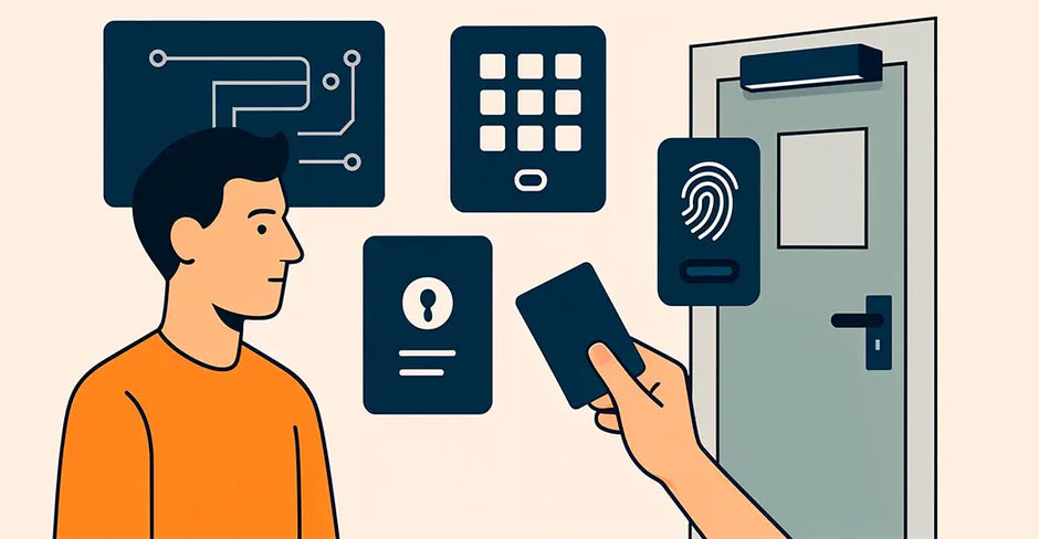
- For card readers: confirm Wiegand or OSDP output using a controller or test tool.
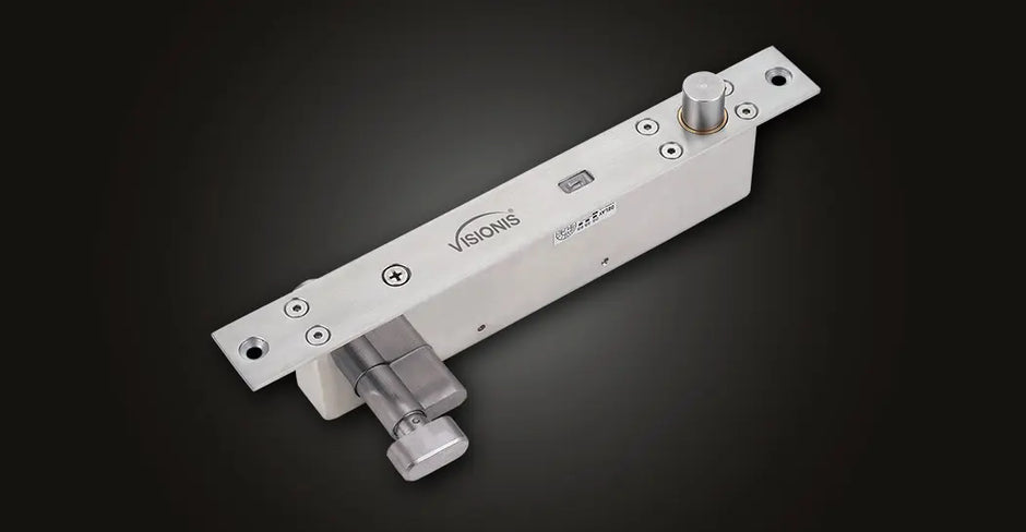
- For electric strikes: cycle the strike open and closed at least 10 times.
- Document any test failures and process RMAs before the installation date.
💡 Pro Tip: Build a simple "test bench" — a piece of plywood with a power supply, terminal strip, and controller — that lets you test any device in seconds without wiring it into the wall.
Mistake #3: Not Checking the Wires for Continuity
Why It Happens
After pulling wire through walls, conduit, and ceiling tiles, many installers assume the wire made it through intact. This is a dangerous assumption. Wire can be nicked by sheet metal edges, pinched by conduit fittings, or broken internally during a difficult pull.
Why It Matters
A broken conductor or unintended short between conductors will cause a device to fail — and without continuity testing, you'll spend hours in electromagnetic lock troubleshooting mode trying to figure out why a perfectly good lock won't hold.
Worse, a short between the lock's positive and negative wires can blow the power supply's output fuse or damage the controller board.
How to Fix It
- Use a digital multimeter set to continuity mode (audible beep) to test each conductor end-to-end after pulling.
- Test for shorts between all pairs of conductors in the same cable.
- For long runs, use a wire tracer/toner to locate breaks without pulling the wire back out.
- Document the voltage reading of each run — it gives you a baseline for future troubleshooting.
💡 Pro Tip: Always test continuity before connecting any device. It takes 60 seconds per run and can save you hours of frustration.
Mistake #4: Using an Inadequate Type of Wire

Why It Happens
Wire is often purchased by whatever is cheapest or most available in the supply house. Installers sometimes use the same cable for everything — power, data, and control — without considering whether it's actually rated for the application.
Why It Matters
Using the wrong wire gauge or type is one of the access control installation mistakes that may not cause an immediate failure, but it will degrade system performance over time.
Undersized wire creates voltage drop — a 12V lock receiving only 10.5V at the end of a long run may not hold reliably.
Unshielded data cables near fluorescent lights or HVAC motors can pick up enough electrical noise to cause card read errors or communication failures.
Wire Selection Guide
- Lock power (up to 50 ft): 18 AWG stranded, 2-conductor
- Lock power (50–150 ft): 16 AWG stranded, 2-conductor
- Lock power (150+ ft): 14 AWG stranded or add a secondary power supply closer to the lock
- Wiegand reader data lines: 22 AWG, 4-conductor shielded (use the standard color code: red/black/green/white), 6-conductor can be used too for additional LED and buzzer controls
- RS-485 communication (OSDP): twisted pair, shielded, 22–24 AWG
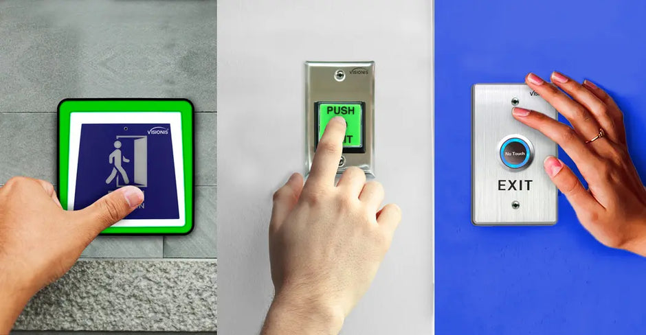
- Door position switch (DPS) / REX: 22 AWG, 2-conductor
💡 Pro Tip: When in doubt, go heavier. Upgrading from 18 AWG to 16 AWG costs pennies per foot but prevents voltage drop problems that are expensive to diagnose and fix later.
Mistake #5: Not Labeling the Wires

Why It Happens
Labeling takes time, and on a fast-paced install, it feels like an optional step. Many technicians plan to remember or document the wiring later — and then never do.
Why It Matters
Six months from now, when a lock stops working and someone needs to trace the wiring, unlabeled cables turn a 15-minute fix into a 2-hour ordeal. This is especially problematic in commercial buildings where multiple doors share a wire closet — a bundle of 20 identical-looking cables is completely useless without labels.
How to Fix It
- Label every wire at both ends before making any connections.
- Use a label maker with heat-shrink or self-laminating labels rated for the environment.
- Include: door number, device type, conductor function, and destination. Example: "D3 – LOCK – PWR+"
- Create a wire schedule spreadsheet and keep it on file for every installation.
- Photograph the labeled wires and the completed panel before closing up the enclosure.
💡 Pro Tip: Use a consistent labeling format on every job. Your future self — and any technician who services the system after you — will thank you.
Mistake #6: Using Devices That Exceed the Power Supply's Capacity

Why It Happens
Many installers grab a power supply from the shelf without calculating the total current draw of all connected devices. Or they select a unit based on a single device without accounting for the full system — controllers, readers, REX sensors, and accessories all draw current simultaneously and must be factored into the total load.
Why It Matters
An overloaded power supply for access control is one of the most damaging mistakes you can make. When the load exceeds capacity, output voltage drops below the rated level. Locks fail to hold, card readers reboot unexpectedly, controllers drop off the network.
Over weeks or months, the overloaded power supply overheats and fails — often at the worst possible time. Replacing a power supply in a finished wall or ceiling panel can be a major project.
How to Size Your Power Supply Correctly
- List every device connected to the power supply and find its current draw (in milliamps) from the spec sheet.
- Add all current draws together to get the total load.
- Multiply the total by 1.25 to get your minimum required power supply capacity (25% safety margin).
- Verify the output voltage matches what your devices require (12V DC vs. 24V DC — never mix).
-
Example:
Lock (500 mA)
+ Controller (300 mA)
+ Reader (150 mA)
+ REX (50 mA)
= 1,000 mA total → minimum 1.25A power supply, so use a 2A unit.
💡 Pro Tip: Use a power supply with a built-in battery backup output (for secondary power in case of an outage) and check that the battery backup capacity is also sized for the full system load.
Mistake #7: Not Following Wiring Instructions or Ignoring the Wiring Diagram
Why It Happens
Experienced installers sometimes skip the manual because they've installed similar products before. New installers may find the diagrams confusing and guess at the connections. Either approach leads to problems.
Why It Matters
Every product in an access control system has specific wiring requirements. The wrong fail state (wiring a fail-safe lock as fail-secure), a missing flyback diode on an electromagnetic lock, or reversed polarity on an RS-485 bus can cause immediate failure, permanent damage to connected equipment, or serious safety issues.
The access control wiring guide in every product manual is not a suggestion — it's the result of engineering and testing.
Industry data consistently shows that wiring errors are among the top three causes of access control system failures during the first year of operation. Following the diagram exactly eliminates this entire category of risk.
How to Fix It
- Read the full wiring diagram before making any connections — even if you've installed the same product before.
- Print or display the diagram on a tablet while you work so you can reference it at every step.
- Pay special attention to fail-safe vs. fail-secure configuration and the correct connection for the free-egress (REX) circuit.
- Never skip the suppression diode on electromagnetic locks — it protects the controller from voltage spikes when the lock de-energizes.
- If the diagram is unclear, call the manufacturer's technical support before proceeding.
💡 Pro Tip: Keep a binder or digital folder of all wiring diagrams for every product on a job site. If a technician returns for service 2 years later, having those diagrams on hand cuts troubleshooting time dramatically.
Final Thoughts
Every one of these access control installation mistakes is preventable.
The common thread running through all seven is the same: taking the time to do the job correctly — aligning components precisely, testing before mounting, verifying wires, using the right materials, labeling everything, sizing equipment properly, and following instructions — is always faster than troubleshooting or redoing work that was rushed the first time.
Here's a quick pre-installation checklist you can use on every job:
✅ Bench-test all devices before mounting
✅ Calculate total current draw and verify power supply capacity
✅ Pull wire and test continuity before connecting anything
✅ Confirm correct wire gauge and type for each run
✅ Label both ends of every conductor
✅ Verify maglock and armature plate alignment before drilling final holes
✅ Have the wiring diagram open and follow it step by step
If you need quality access control products with clear documentation and responsive technical support, browse our catalog. We carry electromagnetic locks, power supplies, controllers, readers, and all the hardware you need for a reliable installation.
Frequently Asked Questions (FAQs)
1. What is the most common reason a magnetic lock loses holding force after installation?
The most frequent cause is improper alignment between the armature plate and the magnet face. Even a small gap prevents full surface contact, which directly reduces the lock's holding strength. Other causes include insufficient power supply voltage and loose wiring connections. Always verify flush contact and confirm the correct voltage is reaching the lock after installation.
2. What wire gauge should I use for a magnetic lock installation?
For most electromagnetic lock installations, 18 AWG stranded copper wire is the standard minimum for runs up to 50 feet. For longer runs — 50 to 150 feet — use 16 AWG to prevent voltage drop. Beyond 150 feet, consider 14 AWG or adding a secondary power supply closer to the lock. For Wiegand reader data cables, always use 22 AWG 6-conductor shielded wire. When in doubt, go with a heavier gauge — it's inexpensive insurance against future performance issues.
3. How do I know if my power supply is large enough for my access control system?
Add up the current draw (in milliamps) of every device the power supply will power: the lock, controller, card reader, REX sensor, and any accessories. Then multiply that total by 1.25 to build in a 25% safety margin. For example, a system drawing 1,000 mA total needs a power supply rated for at least 1.25 A — so a 2 A unit is a practical choice. Also confirm that the output voltage (12V DC or 24V DC) matches what all your devices require.
4. What is the difference between a fail-safe and a fail-secure magnetic lock?
A fail-safe lock releases (unlocks) when power is lost, allowing free egress in an emergency — this is the most common configuration for electromagnetic locks on exit doors. A fail-secure lock remains locked when power is lost, which is used in high-security areas where the door must stay secured even during a power outage. Wiring the wrong fail state for the application is a serious safety and code compliance issue, so always confirm which configuration is required before installation.
5. Do I need to test access control devices before installing them?
Yes — always bench-test every device before mounting it permanently. Apply power to locks and confirm they engage. Test card readers with the controller to verify communication. Cycle electric strikes multiple times. This step takes only a few minutes per device but can save hours of labor if you discover a defective unit after it's already installed in a wall or door frame. Defective-on-arrival products exist in every product category, and testing before mounting is one of the most effective ways to avoid costly reinstallation work.